Abstract
In this paper, design and analysis of a stepped impedance hairpin resonator is presented. The proposed resonator is constructed by parallel connected transmission lines having different characteristic impedances at different locations. Resonance characteristics of the resonator are investigated by locating it to a simple straight transmission line. Depending on this approach, even and odd mode input impedances can be extracted and theoretical response can also be obtained. Besides, effects of the physical dimensions on the frequency response are observed. Additionally, in order to emphasize the utilization advantages of the proposed resonator, current and charge distributions at the resonance frequencies are investigated .The designed stepped impedance hairpin resonator exhibits dual resonance behavior. The second resonance frequency is located approximately at the four times of the first one. The proposed structure has been fabricated and measured in a very good agreement with the predicted results.
Due to the fast progresses in modern communication systems, microwave circuits having more than one operating band have gained a respectable place. Therefore, multiband microwave circuits such as filters, antennas, multiplexers are developed in several ways depending on the utilization of microstrip, waveguides, coplanar waveguides, striplines, etc. Among them, microstrip structures are used more than the others since they can provide design flexibility, low loss, low cost, etc. They are also useful to obtain the desired frequency response easily. For this purpose, many types of microstrip resonators operating at more than one resonance frequency are designed according to the different demands of different communication systems. On the other hand, integration of a circuit into any system brings the requirement of simple resonator topology together.
To date, dual-mode loop resonators, stub loaded resonators, complementary split ring resonators, co-directional split ring resonators have been widely investigated especially through a filter design. Dualmode loop resonators have been developed as circular loop resonators, square loop resonators, fractal resonators, hexagonal loop resonators, etc. They are used to obtain two degenerate modes which can be excited by means of a perturbation element located at the symmetry axis of the resonator. It is a significant problem to control the degenerate modes independently. Thus, analyses of dual-mode loop resonators should be realized to achieve the controlling operation of the degenerate modes. In [1], a dual-mode loop resonator in a circular topology has been firstly introduced and a microstrip bandpass filter has been designed. Coupling descriptions of a dual-mode loop resonator has been achieved due to the various perturbation types including corner cut or patch perturbation elements in [2]. Dual-mode loop resonators have also been utilized in multi-band microstrip filter designs [3-5]. In [6], a fractal stub loaded resonator has been developed to design a dual-band microstrip bandpass filter. Another type of dual-mode loop resonators has been designed as a hexagonal loop resonator [7]. Stub loaded resonators have also been introduced by virtue of short-circuited and open-circuited stubs. Utilization of the stubs is needed to obtain multiple resonance frequencies. In [8, 9], open-/short-circuited stub loaded Л/4 resonators have been designed to obtain dual-band bandpass filter response. On the other hand, a quadband bandstop filter response has been obtained by using dual-mode open loop resonators having thin film capacitors [10]. In this structure, thin film capacitors actually behave as stubs. Additionally, complementary split ring resonators and co-directional split ring resonators having dual resonance behavior have been designed to perform multiband structures [11, 12]. Although dual-mode resonators have been widely examined, triple mode and quad mode resonators have also been developed and utilized for multi-band microstrip filter designs [13, 14].
In this paper, a stepped impedance hairpin resonator located to a simple straight transmission line is analyzed. This transmission line also connects input and output ports to each other. Thus, the proposed structure behaves as a single pole dual-band bandstop filter. Analysis of the resonator is performed by extracting the even and odd mode input impedances. It is observed that there are two resonance frequencies where the second resonance frequency locates at approximately four times of the first one.
Theoretical Model
Proposed stepped impedance hairpin resonator is depicted in Fig. la. As can be seen from the figure, the proposed resonator is connected to a simple straight transmission line which connects input and output ports. The proposed circuit can also be considered as a bandstop filter with single pole. It should be noted that the transmission lines of the resonator are far away from each other so as to prevent extra couplings. Thus, analysis of the structure can be performed by means of transmission line theory. For this purpose, equivalent circuit models due to the even and odd mode excitations are illustrated in Figs. Ib and lc, respectively. As is well known, even mode equivalent half circuit model can be obtained by locating an electrical wall at the symmetry axis of the configuration. In other words, symmetry axis of the structure is considered as open- circuited. From Fig. la, it is clear that five separate transmission lines are appeared under even mode excitation. The first transmission line stated with an electrical length of and characteristic impedance of represent the main simple straight transmission line having a width OfuY. Since it has same impedance with the input and output ports, ^oiis equal to approximately 50 Q. The electrical length can be evaluated by №
where J \ A /is phase constant, d is the physical length of the related C
transmission line. is wavelength which can be found by . In here c is the speed of light, f is frequency and E°rr is the effective dielectric constant. Effective dielectric constant and characteristic impedance of any transmission line can be calculated according to the expressions given in [15]. The second transmission line stated with the electrical length of ө. and the characteristic impedance of ^os represent the vertical transmission line having half width of . It should be noted that the half width of w, jS used since the configuration is investigated as a half circuit and the middle transmission line is divided. The remaining transmission lines stated with
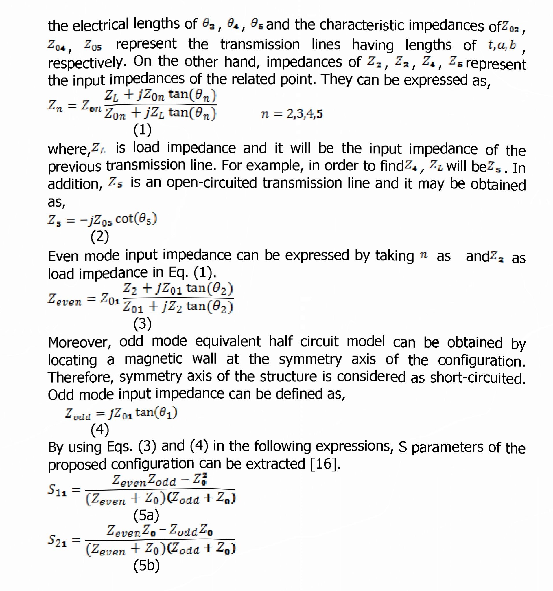
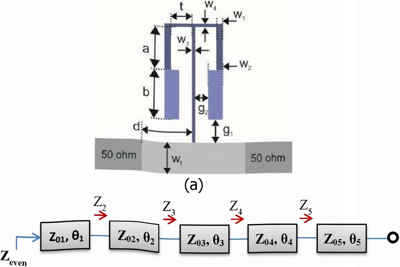
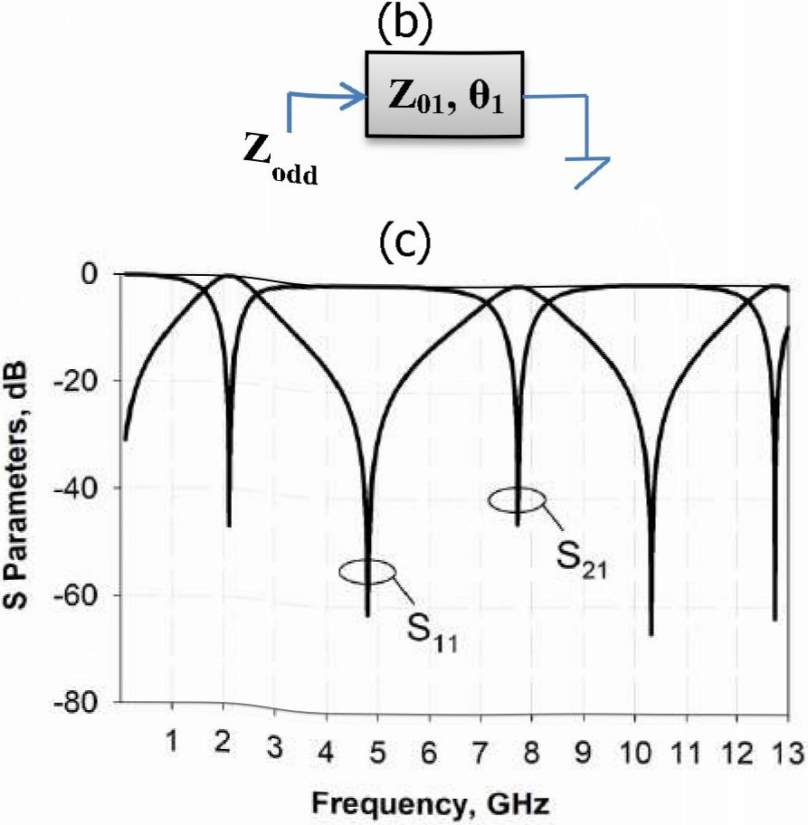
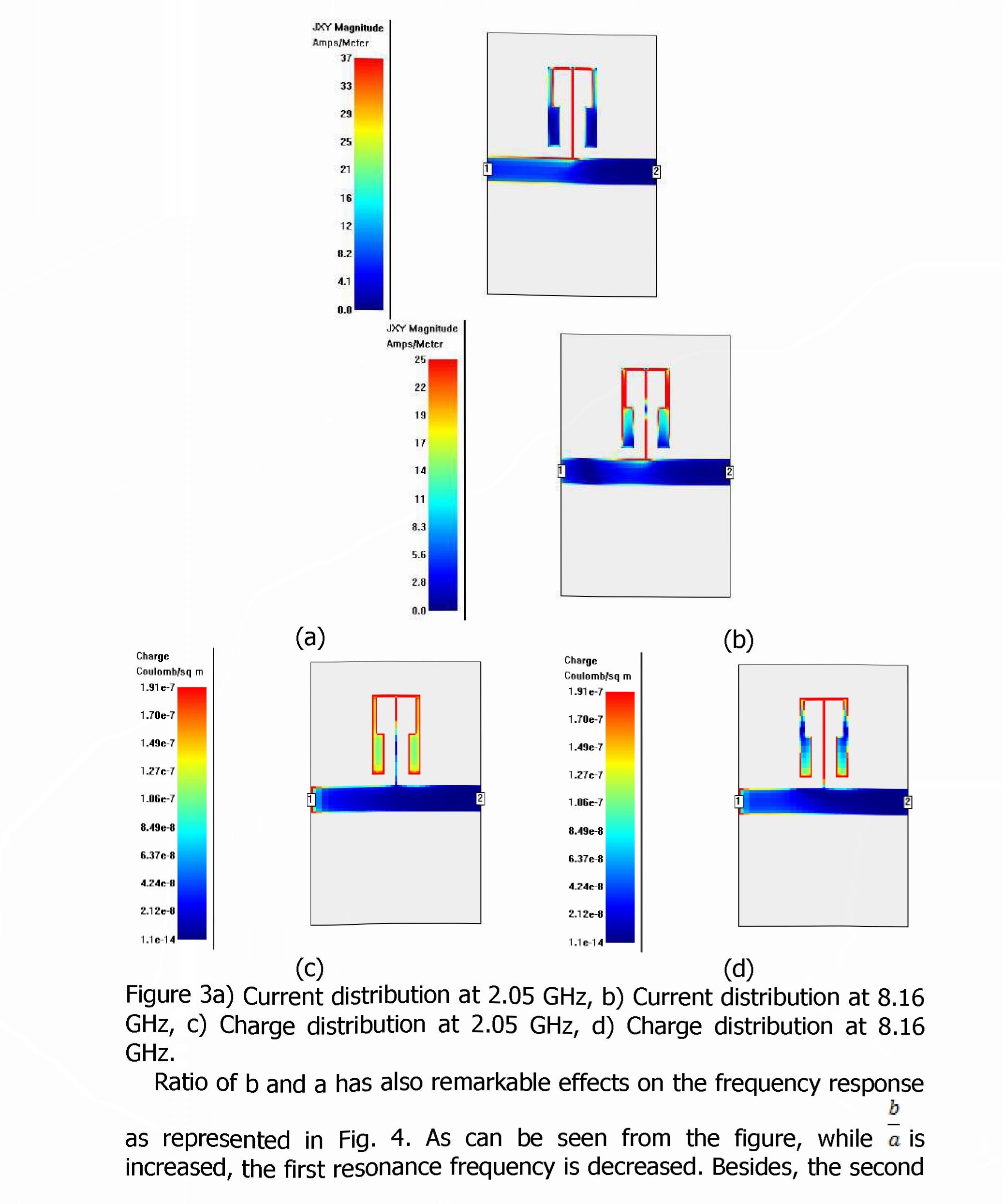
Figure 1 a) Configuration of the single stepped impedance hairpin resonator and its equivalent circuit models for b) even mode, c) odd mode, d) extracted frequency response.
Simulation Results
The designed resonator is simulated by a Full-Wave Electromagnetic Simulator [16]. In the design, an RT/Duroid substrate with a relative dielectric constant of 6.15 and a thickness of 1.27 mm is used. Dimensions shown in Fig- Ia are;
a = 2.6 mm,b = 3.0 mm,W1 = 0,4 mm, W1 = 0.9 mm,W1 = Wt = 0.2 mm,wf = 1.9 mm,d = 3.1 mm, t = 1.3 mm, S1 = 0.4 mm andg, = 0.8 mm.
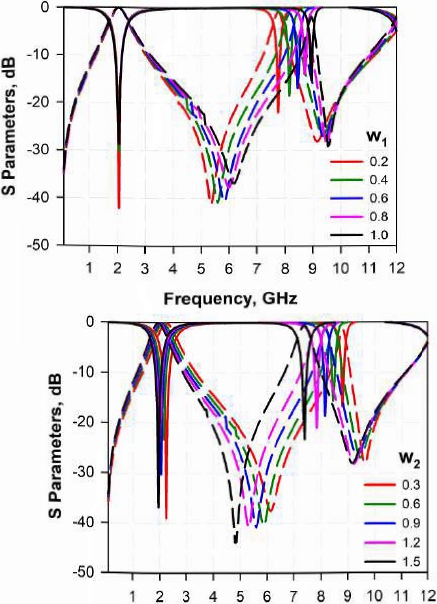
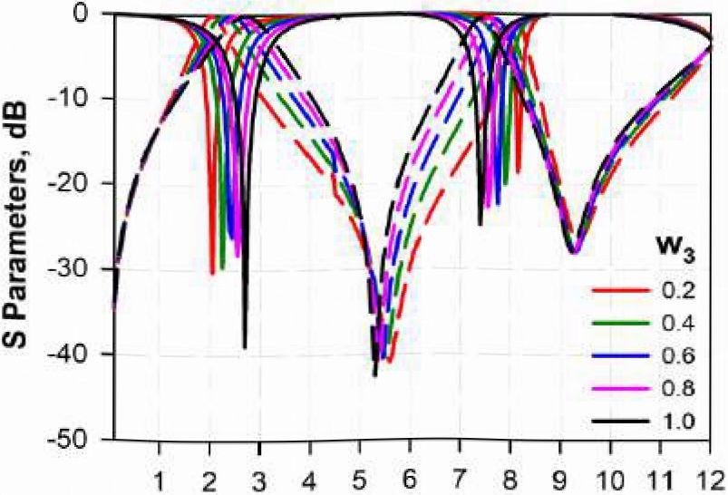
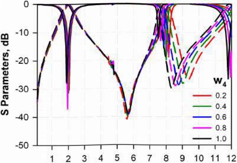
Effects of some parameter changes on the frequency response are depicted in Figs. 2(a-d). In Fig. 2a, ovaries between 0.2 mm and 1.0 mm. It is clear that only the second stopband can be changed, while the first stopband is fixed. Fig. 2b shows the changes of wa in the range of 0.3 mm and 1.5 mm. In here, the second stopband can be changed dramatically as compared to the first stopband. According to the changes in«ra, both stopbands can be simultaneously controlled as shown in Fig. 2c. It should be noted that the first resonance frequency can be increased whiles is increased. However, the second stopband exhibits opposite behavior. Thus, whiles is increased, resonance frequencies of the stopbands are getting closer to each other. Variations of are demonstrated in Fig. 2d. As shown, in a similar manner Withw1 change, the second stopband can be controlled dramatically as compared to the first stopband. Changes in the first stopband are almost negligible. Those parameter investigations are useful to optimize the circuit design.
(b)
Frequency, GHz
Frequency, GHz (c) (d)
Figure 2 Effects of the changes in resonator widths on the frequency responses, a) wi, b) W2, с) и<?, d) W4 (All in mm)
Current and charge distributions of the proposed structure are demonstrated in Figs. 3(a-d). In Fig. 3a and 3b, current distributions are shown at the first and second resonance frequencies, respectively. Charge distributions are also depicted in Fig. 3c and 3d for both resonance frequencies. It should be noted that the current distribution can be observed at the middle high impedance transmission line for the first resonance frequency and it can be observed at the lateral arms at the second resonance frequency. However, charge distribution can be observed everywhere at both resonance frequencies. Thus, it can be said that the second resonance frequency can be controlled by means of the changes in a and b .
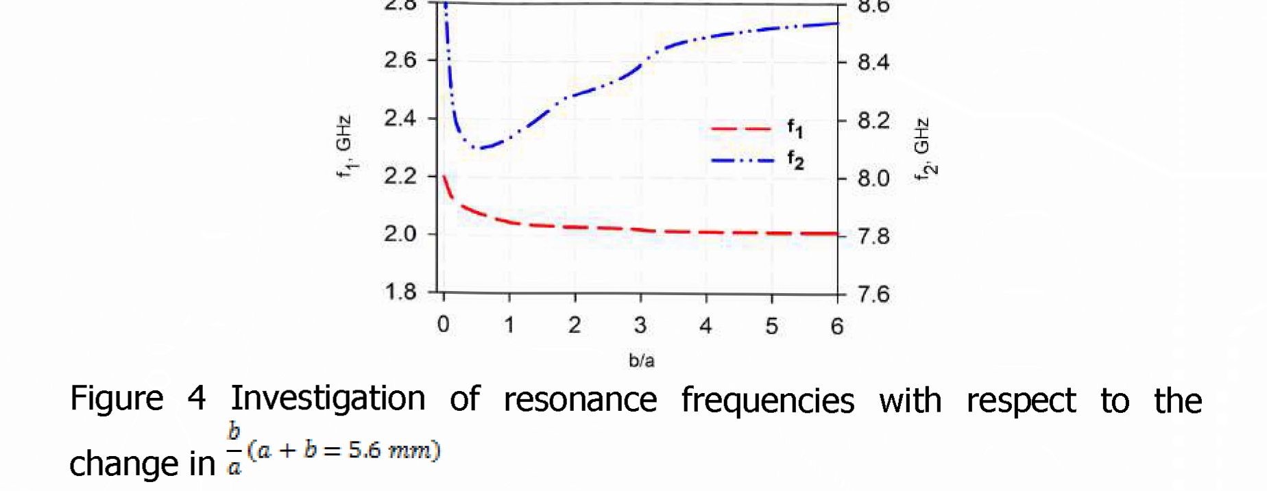
resonance frequency exhibits more different behavior. Depending on the b increment in a, the second resonance frequency firstly decreases and then it begins increasing. It is clear that the proposed structure allows obtaining a ratio between the resonance frequencies as greater than 4. In other words, while the first resonance frequency is/o, the second resonance frequency can be obtained at higher than.
Experimental Studies
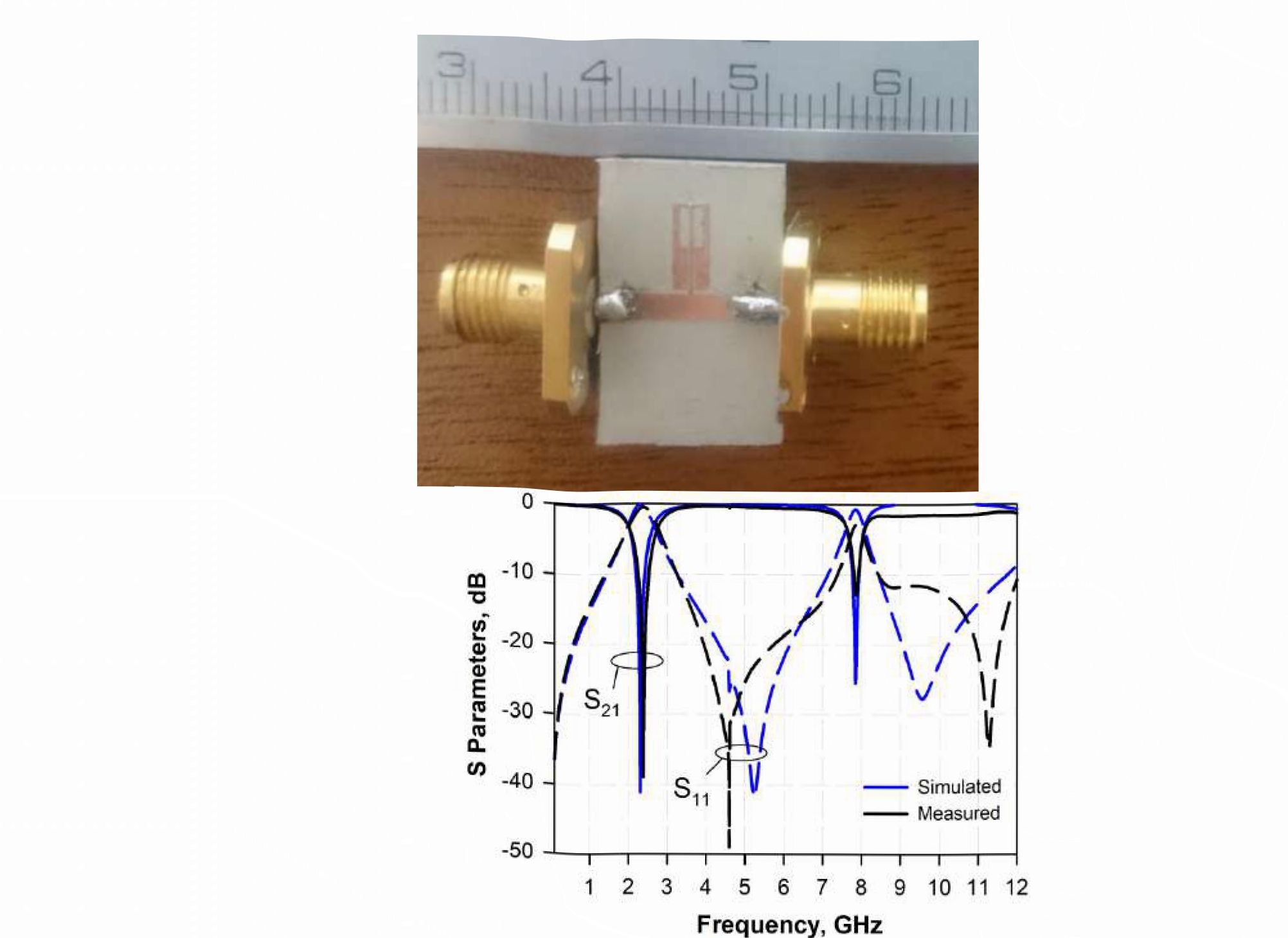
A prototype of the proposed configuration has been fabricated to verify the simulated results. Couplings between the transmission lines at the lateral arms have also been investigated during the experimental studies. For this purpose, dimensions have been revised asa = 2.8 mm and^s = 0 2 mm , photograph of the fabricated filter is illustrated in Fig. 5a. Measurements of the fabricated structure have been realized by a Vector Network Analyzer of HP8720C. Comparisons of the simulated and measured results are also depicted in Fig. 5b. It can be seen that there is a very good agreement with the simulated and measured results. While the first resonance frequency is at about 2.39 GHz and the second resonance frequency can be obtained at 7.87 GHz. When the designed structure has been considered as a single pole bandstop filter, rejection levels at both stopbands could be satisfactorily obtained as better than 12 dB. Additionally, return losses have been observed as better than 2.75 dB at each stopband.
Figure 5a) Photograph of the fabricated filter, b) comparison of the simulated and measured results
Conclusion
A stepped impedance hairpin resonator has been proposed and analyzed. Analysis of the proposed resonator has been performed by extracting the even and odd mode input impedances. Effects of the dimensions of the proposed structure on the frequency response have been investigated. Current and charge distributions have also been introduced to clarify the controlling operation of the resonance frequencies. It has been observed that the second resonance frequency could be obtained at approximately four times of the first one. The designed structure has been fabricated and measured in order to verify the proposed approach. Measurement results exhibit a very good agreement with the simulated results.
The designed structure can be utilized in designs of microstrip filters, multiplexers, antennas, etc. The most significant advantage of the
 122
122
f0
proposed structure is to provide the ratio of+A> between the resonance frequencies. As a future work, it is expected to design a higher order dualband bandstop filter by using the designed resonator.
References
- I. Wolff, "Microstrip bandpass filter using degenerate modes of a microstrip ring resonator," Electron. Lett., vol. 8, no. 12, pp. 302-303, 1972.
- A. Gorur, "Description of coupling between degenerate modes of a dual-mode microstrip loop resonator using a novel perturbation arrangement and its dual-mode bandpass filter applications," IEEE Trans. Microw. Theory Tech., vol. 52, no. 2, pp. 671-677, 2004.
- C. Karpuz, A. K. Goriir, A. Ozek and Z. Karaca, "Design of quadband bandpass filter using nested dual-mode square loop resonators," 2014 44th European Microwave Conference, Rome, 2014, pp. 945-948.
- J. C. Liu, J. W. Wang, B. H. Zeng, D. C. Chang, "CPW-Fed DualMode Double-Square-Ring Resonators for Quad-Band Filters," IEEE Microw. and Wireless Compon. Lett., vol.20, no.3, pp.142,144, March 2010
- J.-C. Liu, F.-S. Huang, C.-P. Kuei, and C.-Y. Liu, "Compact DualMode Double Square-Loop Resonators for WLAN and WiMAX Tri-Band Filter Design," Progress In Electromagnetics Research C, Vol. 38, 101-113, 2013.
- H. T. Ziboon and J. K. Ali, "Compact dual-band bandpass filter based on fractal stub-loaded resonator," 2017 Progress In Electromagnetics Research Symposium - Spring (PIERS), St. Petersburg, 2017, pp. 1815-1819.
- Song, K., Zhu, Y., Zhao, M., Fan, M., and Fan, Y., "Miniaturized bandpass filter using dual-mode hexagonal loop resonator", International Journal of Microwave and Wireless Technologies, vol.9, no.5, pp. 1003- 1008, 2017.
- Z. Zhang, Q. Chu and F. Chen, "Compact Dual-Band Bandpass Filters Using Open-ZShort-Circuited Stub-Loaded$\lambda/4$Resonators," in IEEE Microwave and Wireless Components Letters, vol. 25, no. 10, pp. 657-659, Oct. 2015.
- X. Dong, M. Li, Y. Li and K. D. Xu, "Dual-band bandpass filters using open-/short- circuited stub-loaded quarter-wavelength resonators," 2016 IEEE MTT-S International Microwave Workshop Series on Advanced Materials and Processes for RF and THz Applications (IMWS- AMP), Chengdu, 2016, pp. 1-3.
- C. Karpuz, A. K. Gorur and M. Emur, "Quad-Band Microstrip Bandstop Filter Design Using Dual-Mode Open Loop Resonators Having Thin Film Capacitors," in IEEE Microwave and Wireless Components Letters, vol. 26, no. 11, pp. 873-875, Nov. 2016.
- A. Garcia-Lamperez and M. Salazar-Palma, "Dual band filter with split-ring resonators," 2006 IEEE MTT-S International Microwave Symposium Digest, San Francisco, CA, 2006, pp. 519-522.
- A.K. Gorur, "A novel dual - band bandpass filter using co - directional split ring resonators with closely spaced passbands and wide upper stopband" Int J RFMicrow Comput Aided Eng., 28, 2018.
- C. F. Chen, "Design of a Compact Microstrip Quint-Band Filter Based on the Tri-Mode Stub-Loaded Stepped-Impedance Resonators," IEEE Microw. and Wireless Compon. Lett., vol.22, no.7, pp.357,359, July 2012.
- S. Zhang and L. Zhu, "Compact and High-Selectivity Microstrip Bandpass Filters Using TripIe-ZQuad-Mode Stub-Loaded Resonators," in IEEE Microwave and Wireless Components Letters, vol. 21, no. 10, pp. 522-524, Oct. 2011.
- J. S. Hong and M. J. Lancaster, Microstrip Filters for RFZMicrowave Applications, Wiley, New York, 2001.
- Sonnet User's Manual, Version 16, Sonnet Software, North Syracuse, NY, 2016.